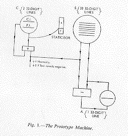
Fig.1. -The Prototype Machine
From the Manchester University Computer Inaugural Conference July 1951 : p5-11
By F. C. Williams, O.B.E., D.S.C., D.Phil., M.I.E.E., F.R.S. and T. Kilburn, M.A., Ph.D.
The computing machine which is now operating at the University of Manchester, represents the culmination of a research project of several years' standing. It seems appropriate to outline the various steps in the development of this project, since these have given the final machine its major characteristics.
The project was initiated at the Telecommunications Research Establishment, Great Malvern, at the end of the war. The development of Radar had produced many new techniques, and it was natural to seek other fields for their application. The National Physical Laboratory were already interested in computing machines, and the A.C.E. was in its early stages.
In the United States, experiments were being made in an endeavour to store radar traces on a cathode ray tube. Another American source reported that the observed phenomena were quite unsuitable as the basis of a computing machine store. The reason given was that the 'memory' was too transient, and thus the record could be read only a very few times before it faded away. In spite of this unfavourable report, the application of cathode ray tube storage to computing machines was considered to be so attractive, if it could be achieved, that a research project with this as its aim was started late in 1946. Looking back, it is amazing how long it took to realise the fact that if one can read a record once, then that is entirely sufficient for storage, provided that what is read can be immediately rewritten in its original position. Experiments with a few binary digits proved that this method of storage by 'regeneration' was possible on the screen of a cathode ray tube, and justified further research.
In January 1947, the project moved to Manchester, but continued to have, and fortunately still has, the active support of the Telecommunications Research Establishment.
The original store used the 'anticipation' pulse system, but since then many other configurations have been tried1. The one in favour at the moment is the defocus-focus system. The successful operation of a single cathode ray tube store, containing 1024 digits, for a period of hours during the autumn of 1947 finally set the main line of the design of the machine, since from then on it was clear that it would use cathode ray tube storage.
The next development was to build a small prototype machine2. This machine,
a schematic diagram of which is shown in Fig. 1, used
one cathode ray tube as a store, S, to hold 32 words, each of 32
digits. It operated serially on the binary digits of a number,
represented negative numbers by complements, and used the single
address code, an instruction being of the form (s,f) where 's' specified a store address, and 'f' the function to be performed. It set the tone
for subsequent Manchester machines in all these respects. A second
single word C.R.T. store was used as the accumulator, A, all calculations
being performed by transfer of numbers between store and
accumulator, whilst a third C.R.T. store, C, held the control number
recording the number of the instruction being performed. Since an
instruction must be read from the store S,
and must then itself control the store selection mechanism via the
staticisor, each instruction must be held in temporary storage as it is
read from S. A second line on the control tube, C, is a highly
convenient place for this temporary storage.

Fig.1. -The Prototype Machine
since the control number and the temporarily stored instruction are
then both fed to the staticisor from the single source, C. The two
lines of C are called the C.I. and P.I. lines, the initials referring to
'control instruction' and 'present instruction' respectively. Taking
the duration of the sweep of one store line, i.e., the number length,
to be one 'beat', and the time taken to find, read and obey an
instruction as being one 'bar,' this machine operated with four beats to the
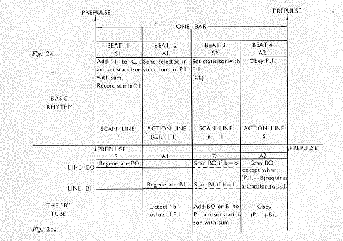
bar as shown in Fig. 2a. In the first beat, S1, the control
instruction was read from C.I., increased by unity to cause the
instructions of a programme to be obeyed sequentially, rewritten in
C.I., and fed to the staticisor. Meanwhile the store S regenerated
some line, say n. In the second beat, A1, the staticisor selected a line
of the store S and fed the appropriate present instruction to the P.I.
line. In the third beat, S2, the present instruction
was read from P.I. and fed to the staticisor, while the store, S,
regenerated line n + 1. In the final beat, A2, the staticisor controlled
the store, and performed the operation specified by the present
instruction. It can be seen that during beats 1 and 2 the machine was
under the control of C.I., while during beats 3 and 4 the machine
operated in a similar manner, but was under the control of P.I. During
the scan beats S1 and S2, successive lines of S, namely n and n + 1 were
regenerated, and the staticisor was set whilst the store was in this
passive state; but during the action beats Al and A2, the store was in
an active state, the line scanned being determined by C.I. or P.I. via
the staticisor. Basically this rhythm of four beats in a bar, which was initiated by a 'prepulse,' has remained unchanged in later machines, though
the addition of facilities of duration greater than one beat has
entailed some modification after the beat A2. This prototype
machine could subtract from the accumulator, write negatively to the accumulator, write from the accumulator to the
store, write to control, and add to control. It also had a test
facility on the sign of the content of the accumulator, which,
if the sign was negative, permitted conditional skipping of an
instruction by adding 2 to C.I. (see Fig. 1). Clearly this
machine had the bare minimum of facilities, but it operated
successfully on small programmes in June 1948.
Up to this point the fact that a full-scale machine with a storage capacity of about 4,000 words would call for over 100 C.R.T. stores had been recognised, disliked, and forgotten. Now this problem had to be faced. Magnetic stores had, of course, been propounded for other machines in a variety of forms; wire, or tape, was proposed for use in conjunction with other stores, and drums suggested as main stores. Wire and tape appeared to have two disadvantages. First, time would be wasted in searching for information along the medium, and secondly, some means of identifying individual digits, or blocks of digits, on the medium would be necessary. Since one objective of machine design was economy and a resulting reduction in the necessary number of C.R.T. stores it was obvious that the best solution would be one that permitted the reloading of a C.R.T. store in the minimum time. The absolute minimum time is the time taken to sweep through all the digits on a C.R.T. at the digit repetition rate. To achieve this it is necessary to make digits emerge from the magnetic store in exact synchronism with the sweeping of spots on the C.R.T. store. This was achieved by using a magnetic drum rotated under the control of a servo system3 that related drum position accurately to the position of a spot sweeping out the pattern on the C.R.T. This involved controlling the position of a drum rotating at about 2,300 r.p.m. to an accuracy of about ½ one hundredth of a degree, but was found to be fairly simple, granted good mechanical design of the drum. This combination of magnetic and C.R.T. storage permits indefinite extension of storage capacity, by using a series of parallel tracks along the length of one drum, and by the addition of further drums. Rapid selection of any track is made possible by providing each with its own magnetic head4.
With this arrangement the magnetic store becomes the major storage element, the C.R.T. store being used as a sort of 'smoother' to cut down the average rate of reference to the magnetic store to a figure appropriate to the 30 milliseconds access time of that store. One cannot be specific without considerable programming experience, about the amount of 'smoothing' that will result, but clearly with a bigger C.R.T. store there need be less frequent reference to the magnetic store. Conversely, more rapid reloading from the magnetic store permits the use of fewer C.R.T.'s. There is room here for a nice economic balance, since longer access time makes possible a more economic magnetic store, but for lack of experience the optimum balance is not yet known.
The synchronised magnetic drum was the second major
controlling factor in the development of machines at
Manchester and continues to provide the bulk of the storage in the
present model.
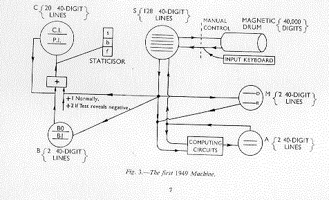
Two further machines incorporating the magnetic store were built during 1949. The first5, shown schematically in Fig. 3, was an extension of the prototype machine with more C.R.T. storage, namely 128 words of 40 digits, and more facilities, including an electronic multiplier6. The accumulator, A, had associated computing circuits for addition, subtraction and three logical operations. Multiplication involved the use of the storage tube M. The multiplicand was stated on the D line and remained there for possible further use after a product was taken; and the multiplier was stated on the R line. Products were added into the accumulator automatically, appropriate account being taken of the signs of D and R. Two 40-digit lines were provided for the accumulator, so that the whole of an 80-digit product of two 40-digit numbers was retained, and any 'rounding off' required was entirely under the control of the programme. Computation using the accumulator was performed modulo 280, by extending 40-digit numbers from the store, S, by 40 copies of their most significant digit.
The magnetic store of this machine had a capacity of 40,960 digits, but loading from the magnetic to the C.R.T. store, and vice versa, could only be achieved manually. Nevertheless, during the summer of 1949, useful work was done on the machine. In particular the Mersenne numbers 2p-1 were tested for primality by the Lucas test. By this means the primality of those Mersenne numbers, already known to be prime from other calculations, were checked. The values of p greater than 257 and less than 354 were also tested and the corresponding Mersenne numbers found to be composite.
A new feature, which was introduced by this machine, and
which in an extended form is a part of the latest machine, was
the 'B' tube. This was a storage tube having two lines B0 and
Bl, either of which could be swept at will under the control of
a single 'b' digit in the instruction, which now took the form
(s,b,f). The output of the B tube was added to P.I. during S2,
before P.I. was used to control the staticisor (see Fig. 2b).
Thus instructions, and in particular their address section,
could be modified in their effect without being modified in
their stored form. In general, line B0 was kept empty, so that
instructions were used unmodified for b=0, but were modified
for b=1. This device was primarily intended as a convenient
means of drifting the effect of a whole block of instructions
by a constant amount, whilst leaving others that were not
'B modified' unaffected. Since then this tube has found many
other similar applications. Instructions could, of course, still
be modified by the more normal processes using the accumulator,
but this was very often inconvenient and wasteful of time
and storage space. The numbers contained on B0 and Bl
were sent from S to the B tube by the standard transfer process,
and arrived in the B tube during the A2 beat.
The second 1949 machine was an extension of the first, the most important development being that by which the magnetic store was brought under the control of instructions from the machine, reference to it being made fully automatic. The design of this facility was influenced by a desire to permit reference, not only to the magnetic store, but also to other possible stores, input and output systems, and so on, without a re-coding of the machine being necessary as these further facilities were incorporated. It was also thought desirable for simplicity and economy to preserve the normal rhythm of the machine as far as possible. To achieve these results a single function, f0, was set aside to be used as part of a standard type of instruction (s, b, f0). In the chosen address 's,' as part of a programme, a key word was placed, the meaning of f0 being that the key word was to be set up on a staticisor. This staticisor was called the 'auxiliary' staticisor and it was set to the key word during the beat A2, by the normal processes of the machine as shown in Fig. 2. By suppressing the prepulse, normally given after the beat A2, for the function f0, the machine was then completely under the control of the key word via the auxiliary staticisor. For magnetic transfers the key word took the form (T, E, F) where T stated the number of the track required on the magnetic drum, E the C.R.T. store required, and F the direction of transfer i.e., whether the content of track T should be placed in the store E, or vice versa. The transfer of information took place, of course, during beats subsequent to A2, and occupied a known time, so that a prepulse could be given after the transfer was complete, and normal operation re-commenced.
In previous machines the input to the machine had been directly to the C.R.T. store from a binary keyboard, and output had been by inspection of a C.R.T. monitor. For this machine, input and output routines were developed which enabled teleprinter equipment to be controlled by the machine. The flow of information to and from the machine was via the last five-digit position in the accumulator. The routing of information between these five places, the C.R.T. store, and the magnetic store was an entirely 'programmed' procedure. This principle of using a programmed input and output, as distinct from employing special equipment, has been largely adhered to since.
A number of programmes were run on this machine before
it was closed down in the summer of 1950. In particular the
Riemann hypothesis was investigated and verified for the range
 .
.
This chiefly involved calculating the Riemann function for about a thousand values of t. For this purpose
the values of log n and n-½ were taken from a table, log
t /2pi was calculated without reference to a table, and the cosines
were obtained by linear interpolation in a table with interval
pi/128. The time for each term of the series was about 160
milliseconds. Further, a problem concerned with ray tracing
through a lens system was investigated. The lens surfaces
were spheres with collinear centres, and the rays traced were
mostly skew.
The machines described in previous paragraphs were entirely concerned with engineering and mathematical experiment. On the basis of experience with these machines, the design of the present machine was laid down in mid 1949 and developed in detail, in close co-operation with Messrs. Ferranti Ltd. A statement of the basic design principles, which also serves as a summary of features already discussed is as follows.
These items were all, of course, included in some form in
the final experimental machine, and in describing the present
machine it will only be necessary to mention improvements
and modifications
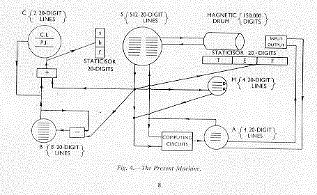
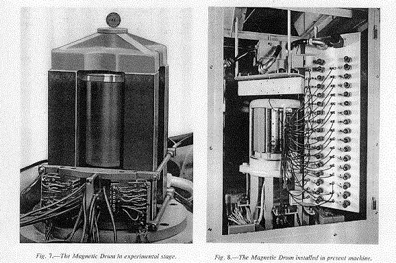
Experience of the large-scale experimental machine showed that the C.R.T. storage capacity of 5,120 digits was rather too small to permit flexibility of programming, and that the subsidiary storage, on the magnetic drum, of 40,960 digits would be quite inadequate for many problems. The C.R.T. storage capacity has therefore been increased to 10,240 digits, using 8 C.R.T.'s. A typical stored pattern on a C.R.T. is shown in Fig. 6. The magnetic storage capacity has been increased to 150,000 digits, provision being made for a further increase to a maximum of about 600,000 digits if this is necessary. The magnetic drum (see Figs. 7 and 8) is 6 inches in diameter, and along its length of 8 inches there is sufficient space to accommodate 256 separate peripheral tracks. Each track holds 2,560 useful digits, the packing density being 165 digits per inch. Key words, 20 digits in length, cause a transfer of information between the contents of a stated track and a stated pair of cathode ray tubes. Alternatively, if it is more convenient, the transfer of information may be between one half-track and one cathode ray tube. In each case the correctness of transfer can be checked by a single instruction, and, in the case of an incorrect transfer, the transfer can be repeated, or the machine stopped.
Selection of a particular track for reading is by electronic switching, and for writing, by relay switching.
The time taken for the check, and for any transfer in which a track is read, is 36 msec. For a transfer in which information is written into a track, this time is increased to 63 msec. to allow time for the relay switching. This discrepancy between the times for reading and writing is not important, because reading is more frequent than writing. This is so because the sub-programmes required during computation are all stored on the magnetic drum.
To increase the speed of operation of the machine by a factor of between 1.8 and 2, the rhythm has been based on a beat whose length is determined by the 20-digit instruction, and not by the 40-digit number. This is advantageous because inspection of Fig. 2 shows that, of the four beats in the bar, only A2 is required to be of number length. Further, for operations involving the B tube and modification of the control instruction, numbers of 20-digit length only are required, so that in these cases the bar is exactly as in Fig. 2, but requires only half the period of time (Fig. 5a). For operations requiring 40-digit numbers, as for example, when the multiplicand is transferred to the multiplier tube, the bar is extended by a further action beat A3, as shown in Fig. 5b. For those operations using the accumulator, which require an 80-digit number (a 40-digit number extended by 40 copies of the most significant digit), the prepulse is still given after A3 to initiate the next bar. This is permissible because only the accumulator is involved in completing the 80-digit operation, and therefore, the last two beats required may be the S1 and A1 beats of the next bar.
The facilities for performing addition, subtraction and three logical operations have been retained, together with signed and unsigned multiplication, in which the 80-digit product of two 40-digit numbers is added to the content of the accumulator. Multiplication in which the product is subtracted from the accumulator is a new facility.
The most important engineering change of the accumulator is in the multiplying circuit. In the experimental machine the multiplication time, which depended on the number of l's in the multiplier, averaged about ten times that for addition. A study of available programmes revealed that, if this multiplying circuit were used in the new machine, about half the computing time of the machine would be spent in multiplication. Consequently, the speed of multiplication has been increased, and, in the new machine, an instruction involving multiplication is selected, interpreted and obeyed in 2.16 msec., as compared with a corresponding time of 1.2 msec., for addition, or any other 40-digit number operation. The increase in speed of multiplication is obtained by using a circuit consisting of a network of adders and delays, arranged in such a way that the sub-products are added together in one operation, instead of sequentially. Although some economy of equipment is achieved by carrying out the multiplication in two parts, controlled respectively by the first and second halves of the multiplier, nevertheless this type of multiplier is expensive and increases the size of the final machine by about 10 per cent. (The machine contains 1,600 pentodes and 2,000 diodes.) This, however, is judged to be worth while when balanced against the resulting overall increase in speed of operation of the machine.
To simplify the standardization of numbers during the course of computation, an instruction has been provided which produces in the accumulator a statement in binary form of the position of the most significant digit of any selected number in the electronic store.
An additional circuit generates (in 5.8 msec.) a 20-digit
random number as a result of a single instruction. This
instruction is used in calculations concerned with stochastic
processes.
This facility has been improved to allow still greater flexibility and economy in programming. Eight 20-digit storage locations can now be selected by the three 'b-digits' of an instruction, and thus any one of eight words may be added to an instruction before it is used.
Further, the B tube has been provided with a subtracting circuit, and a sign-testing circuit. Any line of the tube can, therefore, be used as a 20-digit accumulator for simple arithmetical processes. One important example of this is in counting the number of times that a group of instructions has been obeyed, cycling of control being conditional on the sign of a number in the B tube. By this means four instructions are removed from any loop in which counting is required.
The instructions provided enable a number from the C.R.T. store to be written into, or subtracted from, the B tube; or a number in the B tube to be written into the C.R.T. store. The line of the B tube involved in these instructions is stated by the three 'b-digits.' To avoid the necessity for eight test circuits -- one for each line -- the instruction 'test the sign of B' reads a single circuit, which is recording the sign of the content of that line of the B tube which was last used.
The input/output system is controlled by key words via the magnetic staticisor. The input uses a photo-electric tape reader capable of reading 200 five-digit characters per second. The output is by a mechanical tape-punch and /or teleprinter each capable of printing ten characters per second.
The speed of input is approaching the maximum for this machine if an input programme is required to organize the input information. However, the speed of output, which is twenty times as slow, can only be justified if, in general, the time of output is smaller than, or comparable with, the input and computing times together. If this proves to be untrue, an alternative scheme for input and output which has been designed around punched cards may be incorporated at a later date.
It is not proposed to limit the programme of work on the machine to any particular type of problem, but to cover a range of problems chosen for their diversity. Thus in the immediate future, the following items are among those which will be investigated.
The authors wish to express their gratitude to the Royal
Society, the Ministry of Supply, the Department of Scientific
and Industrial Research, Ferranti Ltd., and the General
Electric Company Ltd., for their generous assistance to this
project.
REFERENCES