THE UNIVERSITY OF MANCHESTER UNIVERSAL HIGH-SPEED DIGITAL COMPUTING MACHINE
Nature, Vol 164, Oct 22,1949, p684.
By Dr. T. KILBURN
Reprinted with permission from Nature 164, 684 Copyright (1949) Macmillan Magazines Limited.
THE electronic computing machine described here has been developed in the Electrical Engineering Laboratories at the University of Manchester under the general direction of Prof F.C. Williams, and with the active assistance of the Telecommunications Research Establishment, Malvern.
The use of electronics in machines of this type follows from the requirement for high-speed operation. A further consequence of this requirement is the desire to eliminate, so far as possible, the necessarily slow process of human intervention, which is essential at every stage of the solution if conventional methods of computing are used. The minimum extent to which this intervention could be conveniently reduced would be to present to the machine an oral or written statement of the problem, in much the same way as problems are presented to a human computer. Research in electrical engineering and mathematics has produced computing machines at Manchester, Cambridge and in the United States, of a type which approximate to this ideal. However, a simple statement of the problem is insufficient. The problem must be programmed, that is, it must be split up into a series of simple operations which the machine can perform. Each operation is represented by an instruction, and these instructions, and the data which they control, are coded in a form which the machine can interpret. During the actual solution of the problem by the machine, however, the need for human intervention is entirely eliminated, for all the data - instructions and numbers - are loaded into the machine initially. The solution then occurs at a speed determined only by the the electronic circuits used. To permit this initial loading, the machine must have a 'memory' or storage facility. One storage system used in the Manchester machine has been fully described elsewhere1. It is clear that as the capacity of the storage is increased, the programming of problems becomes easier; for mathematical operations common to many problems may be programmed, and introduced permanently into the storage of the machine. It will then be necessary to construct only 'master programmes', which call upon these 'sub-programmes' appropriately, and a nearer approximation to the ideal is achieved without further engineering being necessary.
The important engineering requirements resulting from the above discussion are as follows:
- representation and interpretation of data;
- storage, and input and output devices; and
- computing circuits.
These items are now discussed with reference to the machine at Manchester.
Representation and Interpretation of Data
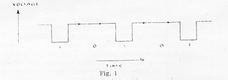
The binary system of numbers1 is used throughout the machine, because of the simplicity and economy with which it can be represented electrically. In this system of numbers, it is only necessary to represent the digits 0 and 1. Thus, in a machine operated in the 'series' mode, the binary number 10101 (decimal 21) is conveniently represented by a train of negative pulses occurring sequentially on a single wire, as shown in Fig. 1.

Now, if the stored items of data are considered to exist in numbered 'addresses', s, in the main storage of the machine, and if, further, the operations or functions, f, which the machine can perform are numbered, then it follows that an instruction, in its simplest form, consists of two numbers (s,f), and may be represented in the same way as a number. In fact, instructions and numbers differ only in the way in which they are used by the machine. Instructions are converted from the 'dynamic' form shown in Fig. 1 into a 'static' form by a set of trigger circuits called a 'staticisor', and are held in this condition for sufficient time to enable, say, a stored number to be 'read' from a selected address, s, and transferred to a selected computing circuit f.
It will be seen that instructions specify addresses, and not the contents of those addresses. Thus, a programme is universal in the sense that, once devised, it can be used to operate on different sets of data without modification.
Storage
The main storage of the machine, which initially holds all the data relevant to a problem, is now discussed.
An important feature of any storage system is its accessibility ratio
alpha = t1/t2,where t1 is the time taken to read a chosen address of the store, and t2 (>= t1) is the time elapsing between the demand for that information being made, and the end of the reading process.
Clearly, it is necessary that the part of the storage to which access is frequently made should have a value of alpha approaching the optimum value of unity, if the time taken in solving a problem is not to be extended by barren periods of waiting. In the electronic storage system1 used, alpha = 1. However, it is unnecessary to have alpha = 1 for all the storage, and, in fact, a magnetic storage system, for which alpha = 1/133, is used to supplement the electronic system. This is made practicable by transferring blocks (tracks) of information between the magnetic and electronic systems; and by having sufficient electronic storage to ensure that, on the average, access to the magnetic storage is not a sufficiently frequent occurrence to affect appreciably the time of solution. With this proviso, magnetic storage is a useful, if not indispensable, adjunct in view of its compactness, permanence of record, and reliability.

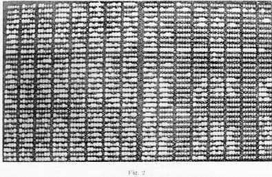
A photograph of the face of an electronic storage cathode ray tube, during the course of the solution of a problem, is shown in Fig. 2. The binary digits 0 and 1 can be seen in the photograph, where they appear as dots, and vertical dashes, respectively. A single storage tube has a capacity of 2,560 digits, arranged in two rasters of television type, where each raster has 32 lines, and each line of a raster holds 40 digits. The lines of the rasters, each of which holds one 40-digit number or two 20-digit instructions, correspond with the storage addresses previously mentioned. It will be seen that the 40 digits of a line are arranged in 8 groups of 5, which is convenient for visual reading of data, and corresponds with teleprinter practice. Input is at present achieved by a keyboard, arranged in the form of a typewriter, by which the state of any digit in the store can be changed from 0 to 1, or vice versa. Output is achieved by visual reading from the known answer lines, in teleprinter code, by inspection of a cathode ray tube face. These methods of input and output will very shortly be replaced by teleprinter apparatus. The conversion from decimal to binary, and from binary to decimal numbering, at the input and output, respectively, will be achieved by the machine itself.
The magnetic system of storage2 uses a 12-in. diameter nickel-plated drum, rotating in synchronism with the scanning of the electronic storage tubes. Each recording track on the drum holds the same number of digits as a cathode ray tube, and the synchronize method of operation ensures one-to-one correspondence between digit position on track and tube.
The present machine has an electronic storage capacity of 5,120 digits, and a magnetic storage capacity of 40,960 digits.
Computing Circuits
In deciding whether or not to include a certain type of computing element in the machine, the frequency of occurrence of that computing operation must be balanced against the time taken for the machine to obey a sub-programme designed to carry out the operation. Thus, special circuits are provided to perform addition, subtraction, multiplication and certain logical operations, but a sub-programme is used to perform division.
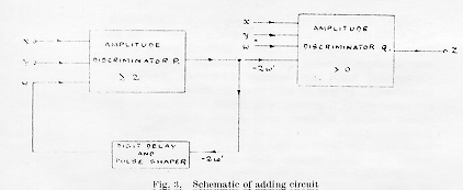
The component elements of the computing and other circuits used are similar to those used in videopulse circuits in radar3. As an example, it will therefore be sufficient to consider schematically one type of adding circuit. The rules of binary addition are such that
        x + y + w >= 2 implies a 1 in w'
        x + y + w <  2 implies a 0 in w'
and     x + y + w - 2w' = z,
where x and y are corresponding digits of the numbers to be added; w' is the carry digit; w is the carried digit (that is, w' delayed by one digit period); z is the sum digit; and x, y, w', w and z are represented by zero or unit amplitude pulses.

These rules are conveniently obeyed by the circuit shown schematically in Fig. 3, the important elements being the two amplitude discriminators, P and Q. These are arranged to deliver an output pulse during a digit period, if the sum of the pulses in the input pulse trains during that period is equal to or greater than 2 and greater than 0 respectively. Discriminator P determines whether a 1 is to be carried, and discriminator Q delivers the output z.
A subtracting circuit may be constructed in a similar manner to obey the rule of subtraction.
In multiplication (the circuit used was developed by A. A. Robinson) the 80-digit product is formed by repeated addition to a running total of the multiplicand, which is suitably shifted (delayed in time) for each 1 in the multiplier.
In addition to these arithmetical circuits, it is useful to be able to operate on data digit by digit, carried digits being suppressed. For this purpose circuits which are much simpler than those mentioned above are provided to perform the logical operations 'and', 'or' and 'not equivalent to'.
Associated with the computing circuits is a storage tube called the accumulator, which holds sufficient lines (two) to record the partial answers. An elementary computation is, in general, performed upon a number, x, obtained by reading the accumulator, and a number, y, obtained by reading a selected address in the main storage. The answer, z, is written into the accumulator over the previous contents, x. At any desired stage of the solution, a partial answer may be read from the accumulator and written into a selected line of the main storage, as a result of a suitable instruction.
The Machine
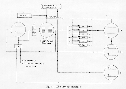
The most important remaining feature of the machine is the control of the order in which the instructions contained in a programme are obeyed, and this is now described, with reference to the schematic diagram of the machine, shown in Fig. 4.

On the left of the figure is 'Control' C, an electronic storage tube, holding two lines, which operates in conjunction with an adding circuit. When a new instruction is required from the instructions stored in one of the main electronic storage tubes, a 'prepulse' initiates a standard sequence of events. Initially, unity is, in general, added to the control instruction line of C (CI), and the new content of CI controls the 'staticisor', S. The new, or 'present', instruction (PI) is then selected from the main electronic storage, and written on the PI line of C, as a result of the condition of S. During this initial phase of the operation, the content of CI has operated as an instruction to extract the next present instruction from the storage. During the final phase of the operation PI, not CI, controls S. Thus in general PI selects a line of the storage, and causes some function to be performed on the contents of that line. When the present instruction has been obeyed, a further prepulse is given automatically, and the standard sequence is repeated. The time elapsing between adjacent prepulses is, except when multiplying, 1.8 m.sec.
It will be understood that the effect of adding unity to CI, after each prepulse, is to cause the instructions in a programme to be obeyed sequentially. Although, in general, this is required, some alternative must be available, if only to prevent instructions being consumed and made redundant at the rate of about 500 per sec. In fact, the same instructions are used repeatedly during the solution of a problem, and this is made possible by having the facility called 'transfer of control', by which the place in the list of instructions, as 'remembered' by CI, can be changed when desired. Such a transfer may be unconditional or conditional. In the unconditional case, use is made of one of two instructions which cause a chosen number to be read from the main electronic storage, and either written over or added to the content of CI. In the conditional case, the programme is arranged so that the sign of the content of the accumulator, A, as determined as a 'test' instruction, is the criterion. (A negative number -q is represented by 240 - q.) If the content of A, which is indicative of the present state of solution, is positive or zero, unity is added to CI after the next prepulse, in the normal manner. If, however, the content is negative, 2 is added to CI at this time, and one instruction in the list is omitted. If this instruction, which may or may not be omitted, is one of the type which modifies CI, a branching point has been created in the list of instructions, and the branch taken is conditioned by the present state of the solution.
On the right of Fig. 4 the accumulator A and its associated computing circuits, any of which may be switched into play by appropriate instructions, are indicated. Multiplication involves the use of the tube M, the multiplicand being stated on the D line, and the multiplier on the R line. Products are added into the accumulator automatically.
Storage tube B is a valuable auxiliary to the machine and is used for modifying instructions. Instructions can, of course, be modified by the normal processes (A and M, etc.) in the same way as numbers, but this is often inconvenient and wasteful of time and storage space. Therefore each instruction (s,f) is preceded by a single digit called the b digit. If b = 0, the content of line B0 of B (normally zero) is added into the present instruction as this instruction is written into the PI line of C, that is, before this instruction is used. If b = 1, the content of line B1 of B is used in the same manner. Numbers are written into B from the main electronic storage, exactly as they are written into M, say.
Loading between the magnetic and electronic stores, and vice versa, is at present achieved manually.
Immediate future development of the machine will include the provision of more lines on the B tube, further extension of the capacity of electronic and magnetic store as required, improved input and output facilities, and automatic interchange of information between electronic and magnetic stores.
I wish to acknowledge my indebtedness to Prof. M. H. A. Newman, and Mr. A. M. Turing for much helpful discussion of the mathematical requirements of digital computing machines; and to Mr G. C. Tootill, who has collaborated in the design of the machine.
References
- Williams, F.C., and Kilburn, T., J. Inst. Elect. Eng., 96, Pt. III, No. 40 (March 1949).
- Unpublished work by J.C. West and G.E. Thomas. For a description of a similar system, see Booth, A.D., Electronic Eng. (July 1949).
- Williams, F.C., J. Inst. Elect. Eng., 93, Pt. IIIA, 303 (1946).

