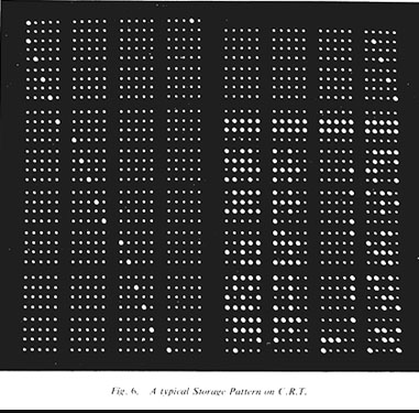
The picture above shows the display from a Display Cathode Ray Tube for a Williams-Kilburn CRT Store (from a Ferranti Mark 1). The bright spots represent 1s and the dim spots represent 0s, representing data in a binary format. Each spot corresponds to an area of electrostatic charge. The display shows 32 40-digit binary numbers with an extra 20-digit line at the top.
In the Baby the layout was 32 rows of 32-bit numbers.
On an actual Williams-Kilburn Tube, the layout of bits was regular and the display of 1s and 0s as phosphor illumination was incidental to the storage mechanism -- in fact it was obscured by the metal pick-up plate over the face of the CRT which sensed the charge. It was also necessary to enclose the CRT in a metal box to protect it from outside electrical interference (e.g. trams). So one or more Display CRTs were provided, each of which held a copy of the current values in a selected storage CRT, laid out in a convenient form for the onlooker. Until the paper tape punch was attached to the Manchester Mark 1, reading a Display CRT was the only form of output.
Note that although the array of bit positions on the corresponding Williams-Kilburn Tube was laid out in a regular array, for user convenience the rows of 20-bit lines are grouped in 4s and 8s, and the bits within a line in groups of 5. Five was chosen because input and output were provided by a five-hole paper tape reader and punch, so this permitted easy correlation between information in the computer store and any information on input/output 5-hole tape that corresponded to it. Note that the least significant digit is on the left hand side of a 5-bit group or a 20-bit line. (See also Programming on the Mark 1.)
Looking more closely, you can see that the integers at addresses (1,2) to (39,40) hold the powers of 2 from 0 to 19, and the integers at addresses (0,1) to (38,39) hold the powers of 2 from 20 to 39 -- a clever shared use of store! Integer (41,42) holds -1, and lines 44 to 63 hold instructions, with field 0-8 giving a 20-bit line address between 0 and 511, field 10-12 a B-line address 0 to 7, and field 14-19 the function code. These instructions contain the routine-changing sequence for Scheme A, and in fact the display is the PERM page (2) of Scheme A.
Both the Williams-Kilburn Tube and the Display CRT were the same size as
for the Baby and the Ferranti Mark 1 (i.e. based on a standard 6 inch CRT).
However for reliability reasons the Ferranti Mark 1 stored only one page per
Williams-Kilburn Tube, thus reverting to the smaller number of bits per
Williams-Kilburn Tube (i.e. the order of 1,000 as in the Baby).
Mark 1 Story :
Introduction,
The Baby,
Manchester Mark 1,
Ferranti Mark 1
Virtual Museum : Main Hall,
Machine Hall
Useful Links : Williams-Kilburn Tube,
F.C. Williams,
Celebrations Page,
Top Page
Context :
50th Anniversary pages
(The Mark 1 story,
Celebrations,
Virtual Museum)
at : the
School of Computer Science,
The University of Manchester
Maintainer : Brian
Napper; last updated Aug. 21st 1998
(full acknowledgements)