
Getting on with the construction
Earlier I described how, at the end of 1995, a team of six volunteer helpers was recruited from among friends and former colleagues. Figure 4 shows the group, together with the team photographer (Suzanne Walker) who had joined later to help record progress. All were motivated by the fascination of reconstructing a piece of history and were proud to use their individual skills to meet the project’s objectives. Most had experience working on vacuum tube technology and had appropriate respect for high voltages. By that time, the feasibility rig was beginning to work at my home, and a technical modus operandi had evolved. Each team member was assigned one section of the computer. His task was to take the circuit diagrams and photographs and study them to become thoroughly familiar with how the system worked. He should then be able to deduce the most likely detailed design for his section as it was on 21 June 1948. As project manager, I attempted to maintain consistency and to arbitrate interpretation of the documents. Everybody worked at home in their spare time, some of the team still being in full-time employment. As the familiarization process progressed, increasingly frequent team meetings were held at the University of Manchester to review progress and solve problems.
The circuit diagrams were the basis for a team member’s investigation. Each diagram represented the circuit of one chassis in the machine, but initially there was hardly any clue as to which chassis was which as seen in the photographs. The panoramic photograph in The Illustrated London News article mentioned earlier did have some annotations as a starting point. By a process of trial and elimination, the team established a plausible overall physical layout, so that a given photograph from one of Alec Robinson’s set dating from December 1948, depicting a chassis, could be matched with a given circuit diagram. The photograph was scanned and presented as an image on a PC using Corel’s Paint Shop Pro, where it could be examined to try to establish two design requirements by determining how the components were laid out on the chassis, and what the dimensions were for the chassis. Although all the chassis had a general similarity (for example, it was found that usually the vacuum tubes were mounted on 2-inch centers), each one was unique for its function.
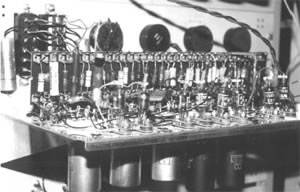
Figure 5. Horizontal time-base chassis in the replica showing vacuum tubes hanging downward and components on tag-boards. Potentiometers and connectors are mounted on the panel.
The tedious process of establishing the positions of the visible holes was done by measuring, on the scanned photograph, the local pixels per inch using known dimensions such as the standard rack drillings. Once a large number of dimensions were measured, patterns began to emerge. For example, the measuring and scaling process indicated that the flanges on the chassis shelf were typically a half inch wide. The recurrence of this dimension, measured and scaled in several places, gave some confidence in its correctness, and a half inch was assumed in those cases where direct measurement was difficult. Chassis that were more distant in the photographs were much harder to measure, and the emerging patterns were used to provide plausible dimensions.
As each chassis’ dimensions were deduced, a computer-aided design (CAD) drawing was created using Evolution Computing’s EasyCad for the pieces of metalwork. These CAD drawings were the first engineering drawings to exist for the part. The drawings of the chassis were then sent to ICL’s engineering workshop for fabrication. The original SSEM used stock steel front panels of various heights, obtained from TRE, and the original shelves were made at the university, cut from a large sheet of tinplate. In 1996, we used the same materials although the new panels were individually fabricated. Approximately 60 chassis had to be designed and made. When the metalwork for a chassis was ready, the team member took it home together with the needed components, and assembled and wired it there according to the appropriate circuit diagram. Figure 5 shows an example of one of the chassis, the horizontal time-base generator.
Study of the photographs yielded many other surprisingly useful details. One example is the tuning condenser visible on one of the chassis. The circuit diagram for the basic clock shows a tuned-plate, tuned-grid oscillator using such a capacitor, which provided a positive identification of the chassis in the photograph. On the nearer chassis in the photographs, it is even possible to identify some of the connecting wires, and this allowed us to reproduce these interconnections in the replica.
An interesting discovery was the way the typewriter push buttons were wired. The illustrations show that the buttons are arranged in an array of eight columns and five rows. The SSEM used a 32-bit word, so only 32 of the 40 buttons were used, the remainder presumably being a contingency in case the SSEM developers wanted to experiment with longer word lengths (which is easy in a serial computer). We had naturally assumed that the assignment of buttons to bits in the word was left to right, then top down, and had wired them in this sequence. However, a piece of BBC newsreel film has survived from 1949, showing about 90 seconds of views of the SSEM/Mark 1. One clip is of Tom Kilburn inserting bits into the memory, and it is clear that he is moving his hand down the columns rather than across the rows. Of such trivia is authenticity attained. Strangely, a few weeks after that discovery, another photograph was found in the university archives, which, when sufficiently enlarged, revealed that each push button had its bit number painted on it. The figures are very faint but confirm the columnwise wiring.
Throughout the project so far, I had attempted to keep a photographic and video record of our activities, but the time needed to do this, and the burden of trying to remember to do it, was becoming onerous. We needed a “project remembrancer,” and so I approached my cousin Suzanne, a former teacher of mathematics and an enthusiastic photographer who was working toward her audiovisual associateship of the Royal Photographic Society, and asked if she would like to join in. She was able to join our Tuesday sessions at the university to contribute a comprehensive pictorial record of the reconstruction activities, resulting in about 700 photographs and more than 10 hours of camcorder footage.