
Obtaining parts
The replica’s authenticity would crucially depend on the availability of original electronic components. The CRTs were known to be type VCR97, the commonest wartime 6-inch radar tube. Many of these have survived in private hands, though of unknown quality, and it was expected that sufficient quantity would be found. Most of the vacuum tubes were type VR91 pentodes (equivalent to the civilian type EF50, designed by Phillips in the late 1930s), and type VR92 diodes (EA50). Again, they were commonplace in 1940s wartime, and enthusiasts would typically have hoarded a dozen or so. We were going to need around 200 VR91s and 400 VR92s. A total of 100 or so of several other types, including the famous type 807 beam power tetrode, were also required. There were no semiconductor devices used in the original. To our amazement, a number of dealers in England still had stocks of these vacuum tubes. We had the feeling that they had been quietly waiting for 40 years for a serious inquiry to come in. But there was also the sense that they were soon going into the scrap, so we were probably just in time. Cliff Jones made the bold decision early in 1995 to fund from his departmental budget the purchase of sufficient vacuum tubes, at a stage when the project was still being debated. All the vacuum tubes appeared to be new and unused in original packing, dating from 1943 to the early 1960s. It was fascinating to find that the 807s were made by RCA in Philadelphia in 1943, shipped across the Atlantic, possibly dodging U-boats, for delivery to the British war effort, and still in perfect working order, fully to specification.
Smaller components such as resistors and capacitors were more difficult to find because they were more likely to have been discarded as low-value items. Furthermore, these components were more likely to have changed their electrical properties or become unusable with the lapse of time. Amateur radio rallies provided some leads to sources among radio hams, and many people came forward with a bag of resistors saying they had kept them so they could make an audio amplifier when they retired, but that it turned out to be easier to go to the shopping center and buy one. One colleague arrived with large boxes of these small components, unused and rescued from a radio repair shop that had closed. Where an authentic old component was not available, a more modern version would be used, and we would record that it was not authentic. In principle, every section of the machine has a Provenance and Authenticity Statement containing such information, although currently records are far from complete.
Hardware items such as plugs and sockets, screw terminals, vacuum tube holders, and even the correct type of nuts and bolts were tracked down and purchased or donated. The numerous variable resistors were identified from the photographs as Colvern wire-wound types. A virtually identical component is still available from UK-based R.S. Components, a large mail-order component supplier, and these were used for reliability. To my regret, the original rubber-covered “push-back” wire could not be found, so we used a modern plastic-covered wire. With hindsight we should have used a much thicker wire to get a truer appearance, but it is too late to change all the wiring now.
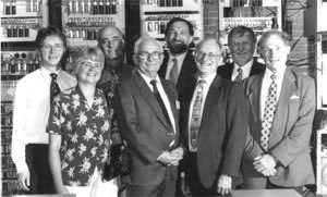
Figure 4. The SSEM Replica technical team in 1998. Adrian Cornforth, Suzanne Walker (project photographer), Charlie Portman, George Roylance, Bill Purvis, Chris Burton, Ken Turner, and Keith Wood.
One particularly satisfying discovery was the exactly correct push-button switch used in the so-called typewriter visible just below the monitor CRT in the photographs, and used to insert single bits into a selected word in memory. I spent many hours gazing at the original photograph through a jeweler’s eyeglass (Figure 1). In one serendipitous moment, the pattern of holes on the panel suddenly brought to mind a set of five push buttons that I had bought in 1953, and which I still had. Furthermore, I still had the relevant catalog of war-surplus electronic equipment, though the dealer had long since disappeared. The catalog cited a Royal Air Force part number, and the part was recognizable in a photograph of the Spitfire fighter’s cockpit: It was a control box for the VHF radio. An inquiry to a dealer in vintage aircraft parts yielded the reply that he had just the number required, though they were 20 times more expensive than they were in 1953.
Surprisingly, the 19-inch racks were hard to find: They have long been superseded by folded sheet steel equipment racks. A call was received one day from a radio amateur who offered two if he could have help retrieving them. He lived in a house in Shrewsbury at the side of the River Severn, and he had used the racks to stop his garden slipping into the river. He said that he was going to move to a new house, so he was happy to let us have them. After sandblasting and painting, they were in excellent condition. Other racks were cut down from some that were surplus to Tony Sale’s Colossus project.
The power supplies for the SSEM are something of a mystery. No pictures or documents exist. They were most probably standard 50-volt, 10-amp telephone exchange modules, as used in Colossus, and indeed in 1948 Williams may have obtained units indirectly from dismantled Colossi. The high-tension supplies of +300 volts, +200 volts, and -150 volts had been obtained by wiring a chain of such modules in series. For the replica it was decided that exact authenticity was not needed; power is provided from a rack containing six modern switchedmode series-connected modules, coincidentally also designed for small telephone exchanges. Approximately 100 amps of 6-volt heater power were also provided, via large transformers formerly used in manual telephone exchanges, and judging from the photographs, probably the type used in the original machine.