
Establishing the original logical and physical
design
As its name implies, the SSEM was very much experimental. The pioneers had no need for formal engineering drawings. Their working documents were a set of hand-drawn schematic circuit diagrams on a table (jokingly called Tom Kilburn’s Office), in the corner of the laboratory, together with their personal notebooks. If a chassis had to be made, it was left to the technician in the workshop to cut sheet metal and physically lay out the components. The machine was constantly being modified and added to, as were the diagrams that always represented the current state. Those circuit diagrams no longer exist, so we have had to rely on secondary sources, described next.
Apart from the CRT storage patents and Kilburn’s CRT report mentioned earlier, the earliest surviving material is a notebook that Geoff Tootill kept and which is currently preserved in the archive at the MSIM. The notebook entries begin with a “First attempt at a BLOCK DIAGRAM” dated 4 June 1948 and continue through to January 1949. The notebook has no complete circuit diagrams, but does contain fragments of circuit designs and many notes about the instruction set, programming issues, and machine operation. This notebook is the only contemporary extant detailed material regarding the events of 21 June 1948. An earlier notebook kept by Tootill was destroyed in a fire some years later.
In August 1948, Alec Robinson made a copy of the computer circuit diagrams in his own notebooks, which he has kept and which survive. Copied in a hurry, they vary in quality and completeness but are probably the nearest to the state of things in June. Robinson had been developing a multiplication unit using a CRT in an adjacent laboratory, and he made the copies because he needed to catch up with the SSEM’s current state prior to attaching the multiplier to the computer.
As mentioned earlier, research students 50 IEEE Annals of the History of Computing Replicating the Manchester Baby Figure 2. The feasibility rig in the author’s office prior to transporting to Manchester. (Photo by Christopher P. Burton.) Thomas and Edwards had joined the team in September 1948. Edwards meticulously copied the lab circuit diagrams into his notebook, which has survived. Many diagrams are dated, from October 1948 through late 1949. Consequently, they reflect a state of the SSEM after months of changes dating from June 1948. However, the diagrams’ completeness, the detailed associated notes on operation, and their delightful neatness (made with pen and ink and ruler, no photocopiers or drafting aids) have made these diagrams the most valuable reference describing the original circuits.
Finally, two important papers that we used as references were published in the Proceedings of the Institution of Electrical Engineers in London. The first, published in 1949, was based on Kilburn’s report, dated 1 December 1947, which describes the CRT storage system.9,10 The second paper, “Universal High-Speed Computers: A Small-Scale Experimental Machine,” was published in 1951.11 This paper, which had been an inspiration to me for decades, is now available online.12 The paper is largely based on Tootill’s MSc thesis and contains some of the key circuit diagrams that can be made to correspond well with those in the notebooks mentioned above.
The SSEM’s physical design was understood in overall terms. The well-known image in Figure 1, for example, shows the general appearance. The 19-inch Post Office racks were standard items with standard drillings. The chassis construction consisted of a folded sheet metal shelf, containing the vacuum tubes hanging downward and the smaller electronic components above. The shelf was fixed to a 19- inch-wide panel that also carried controls, switches, terminals (binding posts), and connectors. The “front” panels are actually at the rear so that the working electronics are accessible. This form of construction was derived from that used experimentally at TRE.
Although the image in Figure 1 is often described as a photograph of the Baby machine, it actually shows an intermediate stage, beginning to resemble the University Mark 1, and was probably taken around April 1949. There is no known photograph of the machine from June 1948.
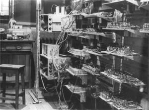
Figure 3. Photograph taken by Alec Robinson on 15 December 1948 showing two of the CRT storage boxes (center). The racks on the right are part of the Multiplication Unit, which had been added to the SSEM at that date.
A panoramic view of the machine was published in The Illustrated London News in June 1949.13 On my inquiring about that picture, Tootill asserted that it was actually a composite view made up of about 24 separate photographs taken by Robinson much earlier than the publication date, and that the composition had been done by the London Electrotype Company presumably entirely by photographic methods. Robinson still possessed most of the 35-mm negatives of those photographs, and an entry in his notebook showed that they were taken on 15 December 1948. They are the earliest extant photographs of the machine. Figure 3, one of those photographs, shows two shielding boxes each containing a storage CRT. The “haywire” (experimental) nature of the machine is evident.
Our goal was specifically to replicate the machine as it was on 21 June 1948. The circuit diagram fragments and photographs were the key sources in our achieving authenticity. However, an irreplaceable supplement was the willingness of the original team to recall their memories of the machine. Williams died in 1977, but Kilburn, Tootill, Robinson, and Edwards were all happy to be interviewed, and Thomas—living in Australia—was consulted by email. One interesting outcome of the interviews was that, often toward the end of a discussion, useful bits of information would emerge partly from the interviewee’s recognizing some document or photograph that triggered a secondary thought. It seems doubtful if those items would have emerged without the artifacts to do the triggering.
Kilburn and Tootill saw the feasibility rig in operation in March 1996, and they were inspired to try to rediscover the coding of the first program. They put a great deal of effort into that research to make possible the goal of rerunning the first program exactly. They com- July–September 2005 51 Figure 3. Photograph taken by Alec Robinson on 15 December 1948 showing two of the CRT storage boxes (center). The racks on the right are part of the Multiplication Unit, which had been added to the SSEM at that date. (Courtesy of the School of Computer Science, the University of Manchester.) Encountering a real working CRT storage system again brought back many memories of the time and that this helped them to establish the authentic code.